|
|
|
|
|
UMTS Power Control
Open loop power control is the ability of the UE transmitter to sets its output power to a specific value. It is used for setting initial uplink and downlink transmission powers when a UE is accessing the network. The open loop power control tolerance is ± 9 dB (normal conditions) or ± 12 dB (extreme conditions)
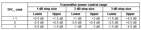
Inner loop power control (also called fast closed loop power control) in the uplink is the ability of the UE transmitter to adjust its output power in accordance with one or more Transmit Power Control (TPC) commands received in the downlink, in order to keep the received uplink Signal-to-Interference Ratio (SIR) at a given SIR target. The UE transmitter is capable of changing the output power with a step size of 1, 2 and 3 dB, in the slot immediately after the TPC_cmd can be derived. Inner loop power control frequency is 1500Hz.
The serving cells estimate SIR of the received uplink DPCH, generate TPC commands (TPC_cmd) and transmit the commands once per slot according to the following rule: if SIRest > SIRtarget then the TPC command to transmit is "0", while if SIRest < SIRtarget then the TPC command to transmit is "1". Upon reception of one or more TPC commands in a slot, the UE derives a single TPC command for each slot, combining multiple TPC commands if more than one is received in a slot. Two algorithms are supported by the UE for deriving a TPC_cmd. Which of these two algorithms is used, is determined by a UE-specific higher-layer parameter, "PowerControlAlgorithm".
Algorithm 1:
The power control step is the change in the UE transmitter output power in response to a single TPC command
Algorithm 2:
If all five estimated TPC command are "down" the transmit power is reduced by 1 dB
If all five estimated TPC command are "up" the transmit power is increased by 1 dB
Otherwise the transmit power is not changed
Transmitter power control range
The transmit power of the downlink channels is determined by the network. The power control step size can take four values: 0.5, 1, 1.5 or 2 dB. It is mandatory for UTRAN to support step size of 1 dB, while support of other step sizes is optional. The UE generates TPC commands to control the network transmit power and send them in the TPC field of the uplink DPCCH. Upon receiving the TPC commands UTRAN adjusts its downlink DPCCH/DPDCH power accordingly.
Outer loop power control is used to maintain the quality of communication at the level of bearer service quality requirement, while using as low power as possible. The uplink outer loop power control is responsible for setting a target SIR in the Node B for each individual uplink inner loop power control. This target SIR is updated for each UE according to the estimated uplink quality (BLock Error Ration, Bit Error Ratio) for each Radio Resource Control connection. The downlink outer loop power control is the ability of the UE receiver to converge to required link quality (BLER) set by the network (RNC) in downlink.
Power control of the downlink common channels are determined by the network. In general the ratio of the transmit power between different downlink channels is not specified in 3GPP specifications and may change with time, even dynamically.
Additional special situations of power control are Power control in compressed mode and Downlink power during handover.
Further reading: 3GPP TS 25.101, 25.133, 25.214, 25.215, 25.331, 25.433, 25.435, 25.841, 25.849
|
|