|
|
|
|
|
Paging
The Paging Channel (PCH) is a downlink transport channel. The PCH is always transmitted over the entire cell. The transmission of the PCH is associated with the transmission of physical-layer generated Paging Indicators, to support efficient sleep-mode procedures.
Paging Channel selection
System information block type 5 (SIB 5) defines common channels to be employed in Idle mode. In a cell, a single or several PCHs may be established. Each Secondary Common Control Physical Channel (SCCPCH) indicated to the UE in system information may carry up to one PCH. Thus, for each defined PCH there is one uniquely associated PICH also indicated.
In case that more than a single PCH and associated PICH are defined in SIB 5, the UE shall perform a selection according to the following rule:
The UE shall select a SCCPCH from the ones listed in SIB 5 based on IMSI as follows:
"Index of selected SCCPCH" = IMSI mod K,
where K is equal to the number of listed SCCPCHs which carry a PCH (i.e. SCCPCHs carrying FACH only shall not be counted). These SCCPCHs shall be indexed in the order of their occurrence in SIB 5 from 0 to K-1.
"Index of selected SCCPCH" identifies the selected SCCPCH with the PCH and the uniquely associated PICH to be used by the UE.
If the UE has no IMSI, for instance when making an emergency call without USIM, the UE shall use as default number IMSI = 0.
The UE may use Discontinuous Reception (DRX) in idle mode in order to reduce power consumption. When DRX is used the UE needs only to monitor one Page Indicator, PI, in one Paging Occasion per DRX cycle.
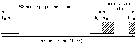
The Paging Indicator Channel (PICH) is a fixed rate (SF=256) physical channel used to carry the paging indicators. The PICH is always associated with an S-CCPCH to which a PCH transport channel is mapped. Picture below illustrates the frame structure of the PICH. One PICH radio frame of length 10 ms consists of 300 bits. Of these, 288 bits are used to carry paging indicators. The remaining 12 bits are not formally part of the PICH and shall not be transmitted (DTX). The part of the frame with no transmission is reserved for possible future use.
Structure of Paging Indicator Channel (PICH)
Two Paging Procedures:
Paging procedure is used to transmit paging information to selected UEs in idle mode, CELL_PCH or URA_PCH state using the paging control channel (PCCH). Upper layers in the network may request paging, to e.g. establish a signalling connection. UTRAN may initiate paging for UEs in CELL_PCH or URA_PCH state to trigger a cell update procedure. In addition, UTRAN may initiate paging for UEs in idle mode, CELL_PCH and URA_PCH state to trigger reading of updated system information. UTRAN initiates the paging procedure by transmitting a PAGING TYPE 1 message on an appropriate paging occasion on the PCCH.
UE dedicated paging procedure is used to transmit dedicated paging information to one UE in connected mode in CELL_DCH or CELL_FACH state. Upper layers in the network may request initiation of paging. For a UE in CELL_DCH or CELL_FACH state, UTRAN initiates the procedure by transmitting a PAGING TYPE 2 message on the DCCH using AM RLC.
Two Paging Message Types:
PAGING TYPE 1 message is used to send information on the paging channel. One or several UEs, in idle or connected mode, can be paged in one message, which also can contain other information
PAGING TYPE 2 message is used to page an UE in connected mode (CELL_DCH or CELL_FACH state), when using the DCCH for CN originated paging.
PICH / S-CCPCH timing relation
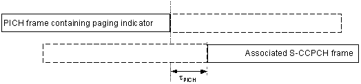
Picture below illustrates the timing between a PICH frame and its associated single S-CCPCH frame, i.e. the S-CCPCH frame that carries the paging information related to the paging indicators in the PICH frame. A paging indicator set in a PICH frame means that the paging message is transmitted on the PCH in the S-CCPCH frame starting tPICH chips after the transmitted PICH frame.
Timing relation between PICH frame and associated S-CCPCH frame
tPICH = 7680 chips (3 slots)
Paging Block Periodicity (PBP): Period of the occurrence of Paging Blocks. (For FDD, PBP = 1).
Paging occasion: (FDD) The SFN of the PICH frame where the UE monitors its paging indicator (i.e. the SFN of the PCCPCH frame in which the PICH frame begins).
Further reading: 3GPP TS 25.211 25.304
|
|