|
|
|
|
|
Compressed Mode
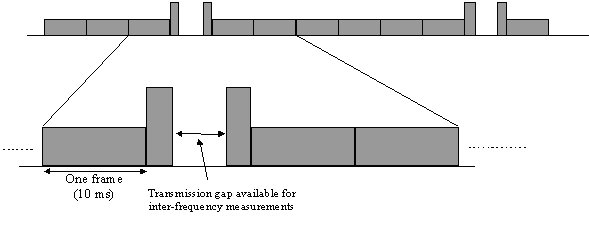
During inter-frequency handover the UEs must be given time to make the necessary measurements on the different WCDMA carrier frequency. 1 to 7 slots per frame can be allocated for the UE to perform this intra frequency (hard handover). These slots can either be in the middle of the single frame or spread over two frames.
This compressed mode operation can be achieved in three different methods:
Decreasing the spreading factor by 2:1. This will increase the data rate so bits will get sent twice as fast.
Puncturing bits. This will remove various bits from the original data and hence reduce the amount of information that needs to be transmitted.
The higher layer scheduling could also be changed to use less timeslots for user traffic.
From the 3GPP TS 25.212:
In compressed frames, Transmission Gap Length slots from Nfirst to Nlast are not used for transmission of data. As illustrated below, the instantaneous transmit power is increased in the compressed frame in order to keep the quality (BER, FER, etc.) unaffected by the reduced processing gain. The amount of power increase depends on the transmission time reduction method. What frames are compressed, are decided by the network. When in compressed mode, compressed frames can occur periodically, or requested on demand. The rate and type of compressed frames is variable and depends on the environment and the measurement requirements.
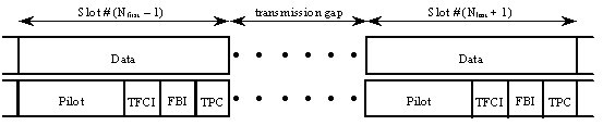
The frame structure for uplink compressed frames is illustrated below.
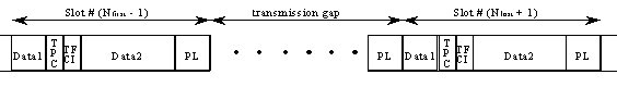
There are two different types of frame structures defined for downlink compressed frames. Type A maximises the transmission gap length and type B is optimised for power control. The frame structure type A or B is set by higher layers independent from the downlink slot format type A or B.
With frame structure of type A, the pilot field of the last slot in the transmission gap is transmitted. Transmission is turned off during the rest of the transmission gap (below).
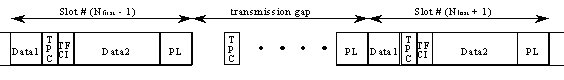
With frame structure of type B, the TPC field of the first slot in the transmission gap and the pilot field of the last slot in the transmission gap is transmitted. Transmission is turned off during the rest of the transmission gap (below).
Further reading: 3GPP TS 25.212
|
|